Arcade Button Arm
For my machine design course, I was tasked with the development of a four-bar, motor driven, linkage that needed to mount to a playing field and press as many buttons as possible in one minute.

-
A member of a five person team tasked with developing a solution to a chosen engineering problem.
I was the primary engineer in charge of:
Optimizing linkage for speed and accuracy while minimizing device volume.
Designing low-profile mounting for integration of the device onto playing field.
Designing linkage joints to minimize friction when driven by motor.
Developing motor mount and gear hubs for the motor transmission.
-
Product Development, Design for Manufacturing, CNC & CAD/CAM, Motor PWM Control, Linkage Design, Dynamic Analysis
Design Phase
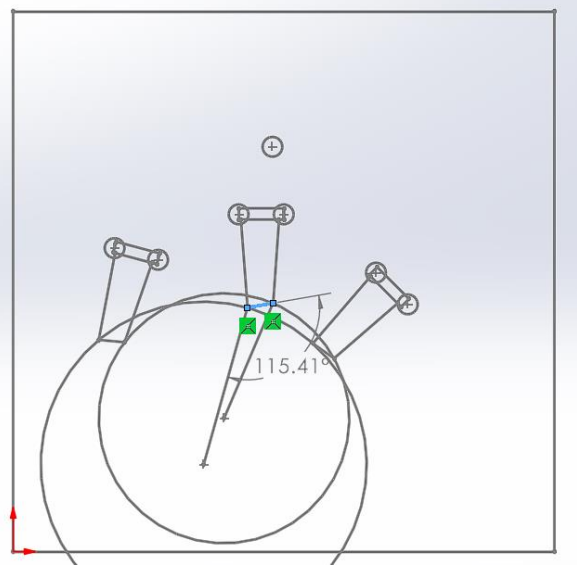
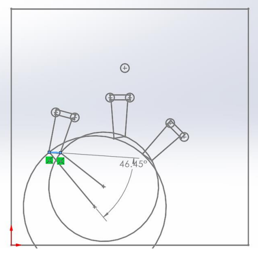
To begin this project, I took charge in the design of the linkage to reach all button positions on the playing field. This was done with a geometric linkage design method.

Links were then designed and manufactured using a water-jet.
The third link, called the coupler, was designed to hold a button-pressing mechanism
This design was not only to engage each button pair, but the bonus button as well. The coupler was created to be lightweight, to limit the loading on the input motor.
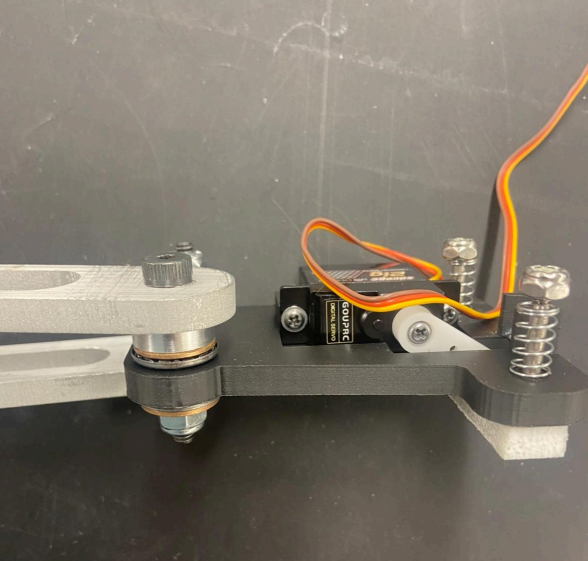
A joint design was selected to connect each linkage member while minimizing friction. This was critical to the functionality of the mechanism, as more friction would result in the linkage’s inability to move quickly between button positions.
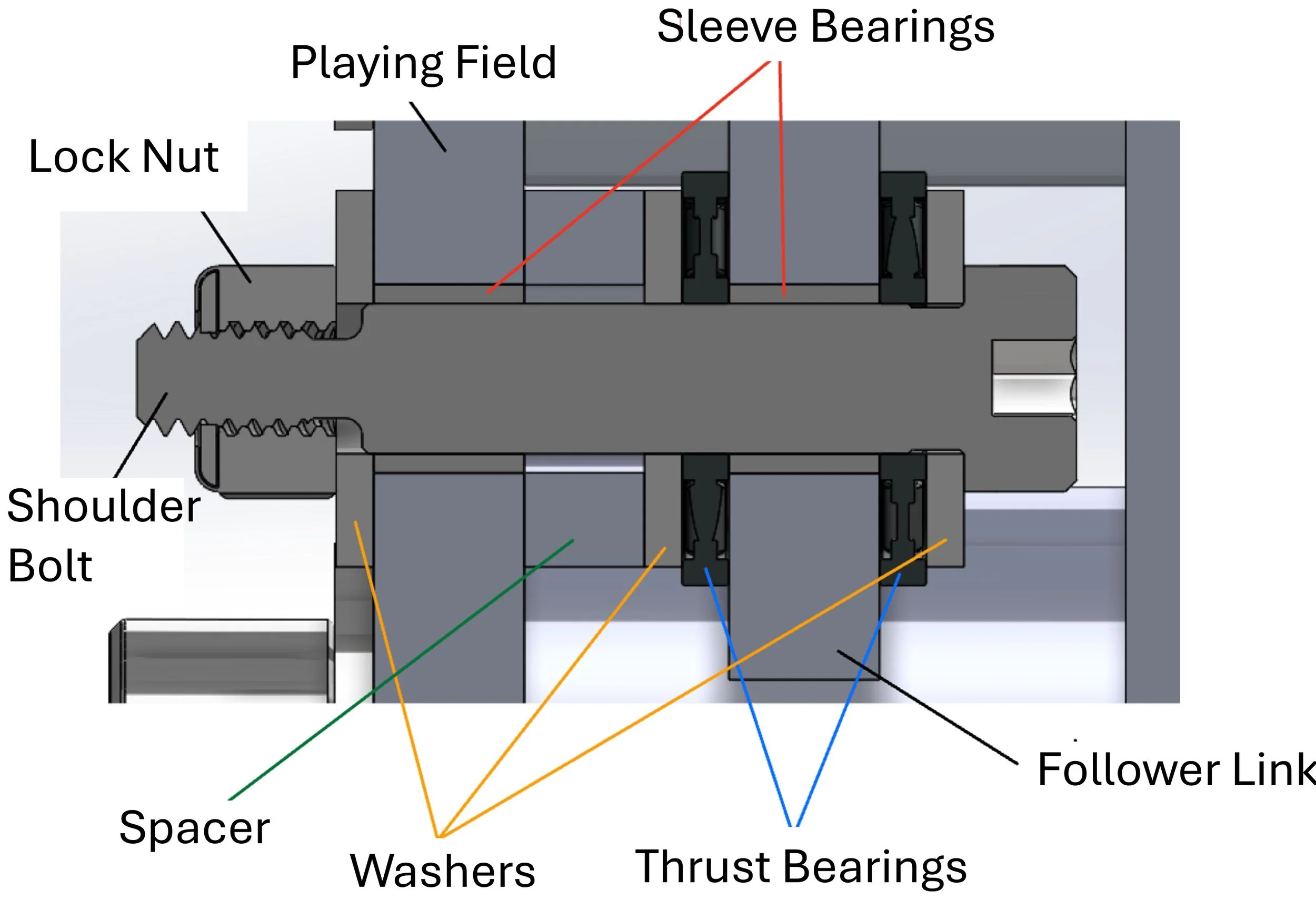
Utilizing needle thrust bearings, oil sleeve bearings, and oil embedded washers, the following design was implemented.
A transmission ratio was selected based on the total moment of inertia of the linkage mechanism. Using this ratio, a gear and pinion were mounted with hubs onto the driving link and motor, respectively.
Manufacturing Phase
In this phase of the development, the linkage mechanism was finalized using several different manufacturing techniques.
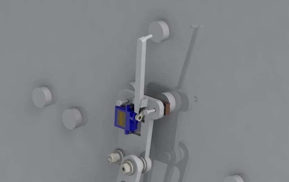
3D Printed Coupler with mounted servo and button pair mechanism.
Links and Base Plate were manufactured using a water-jet and finished with sandblasting.
Transmisson Hubs and Spacers were fabricated using 3.5 Axis CNC Mills.
Motor mounting was manufactured with a CNC Tormach Mill.

Spacer shown with shoulder bolts for the ground plate to rigidly connect the mechanism to playing field.

Assembled mechanism

Transmission hubs interfacing with the links and motor.
Tuning
Once the mechanism was completed, the motor was connected to an arduino to control its position. The mechanism was commanded using PID control using the following scheme:
Position was zeroed at the far left button position using a limit switch.
Approximate positions of button pairs were logged into the arduino by manually moving the linkage to each pair position and then recording the corresponding encoder count.
Arduino was connected to the playing field board to read its output signals, so the linkage could move to the lit button pair.
The linkage speed between each pair location was iteratively increased while maintaining its accuracy using PID control.
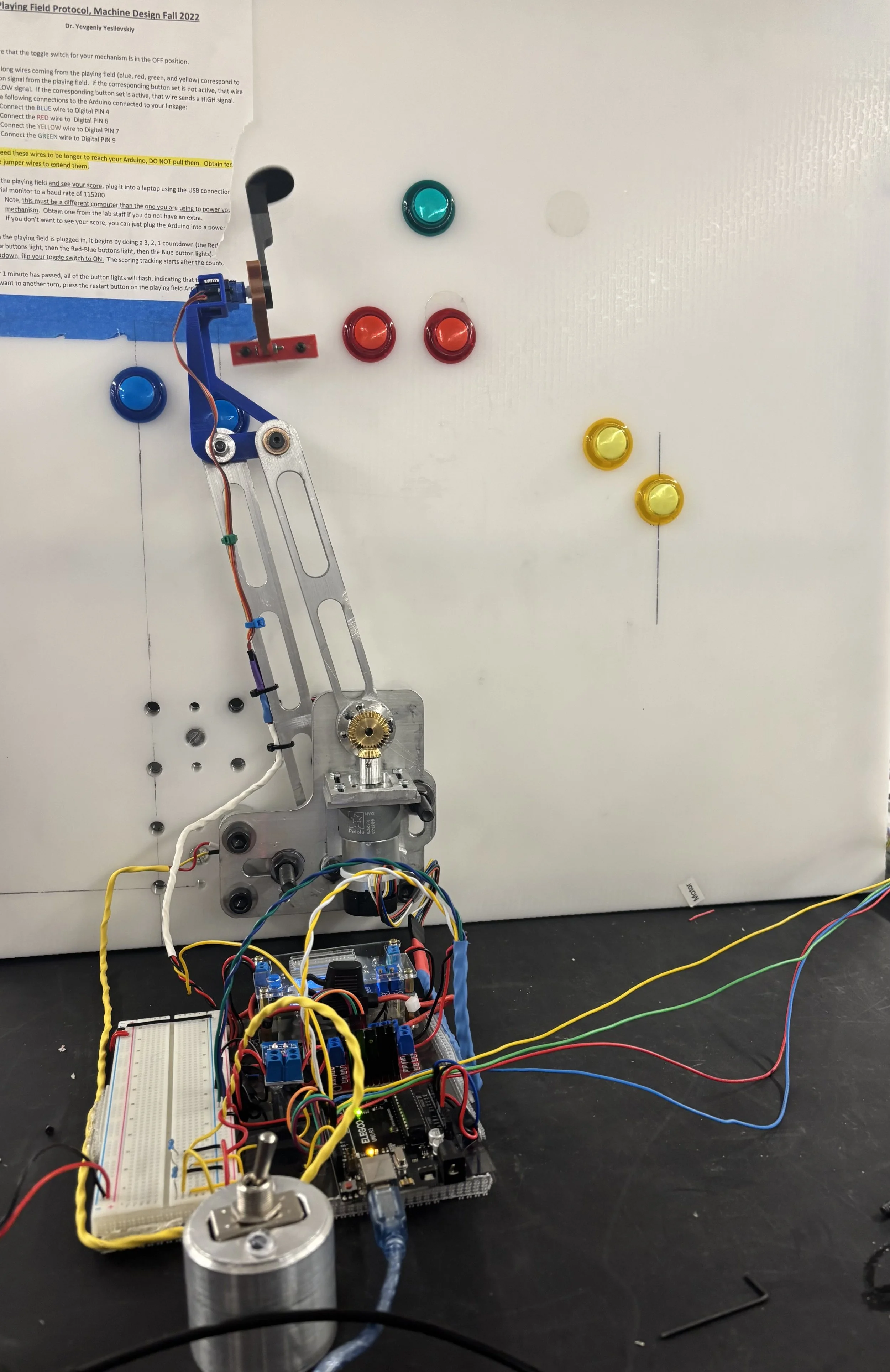
Completed Linkage Mechanism and Electronics.
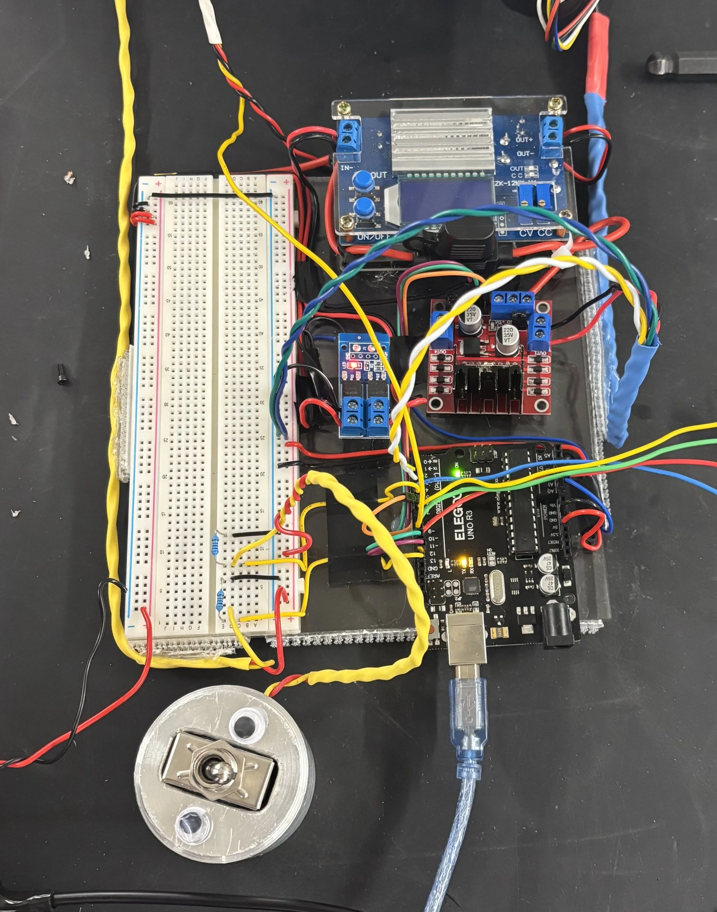
Electronics: H-Bridge, Arduino UNO, DC-DC Converter, Kill Switch
Outcome
Linkage was tested and performed in moving to each button pair and the bonus button, pressing 142 buttons in 1 minute. This was well above the average for other teams, which was around 90-100 buttons in 1 minute. The minimized volume of the mechanism and base plate, scaled by the linkage performance, was in the top 10% of the class.